Hiển thị các bài đăng có nhãn Fortigate. Hiển thị tất cả bài đăng

Thứ Ba, 27 tháng 2, 2018

Cấu hình IPS, DOS trên Firewall Fortigate


Tấn công DoS là một kiểu tấn công mà một người làm cho một hệ thống không thể sử dụng, hoặc làm cho hệ thống đó chậm đi một cách đáng kể với người dùng bình thường, bằng cách làm quá tải tài nguyên của hệ thống. Nếu kẻ tấn công không có khả năng thâm nhập được vào hệ thống, thì chúng cố gắng tìm cách làm cho hệ thống đó sụp đổ và không có khả năng phục vụ người dùng bình thường đó là tấn công Denial of Service (DoS). Mặc dù tấn công DoS không có khả năng truy cập vào dữ liệu thực của hệ thống nhưng nó có thể làm gián đoạn các dịch vụ mà hệ thống đó cung cấp.Tấn công DoS là kiểu tấn công vô cùng nguy hiểm cho nên phải có biện pháp phòng chống cho kiểu tấn công này.Sau đây mình xin hướng dẫn cấu hình phòng chống DoS và IPS Signature trên tường lửa Fortigate 5.2
Bước 1: Các bạn vào System--> 
Feature Select, mở tính năng Intrustion Protection rồi chọn apply như hình bên dưới :


Bước 2: Các bạn vào security Profiles-->Intrustion Protection-->Turn on các Rate based Signatures
Bước 3: Ở mục Pattern Based Signatures and Filters các bạn chọn và edit và block các signatures rồi chọn ok 


Bước 4: Add IPS vào policy mà mình muốn thực thi:

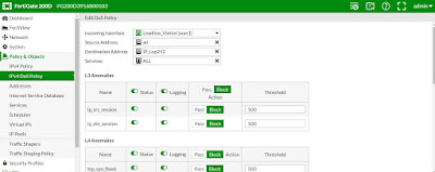
Bước 5: Tạo rule để ngăn chặn tấn công Dos . Các bạn vào mục Policy & Objects--> IPV4 Dos Policy > Create New và làm theo như hình bên dưới :

Bước 6: Các bạn có thể xem kết quả ở mục: Fortiview-->Threats để xem kết quả.

Như vậy các bạn đã hoàn thành cấu hình IPS/Dos trên Firewall Fortigate


Thứ Hai, 11 tháng 12, 2017

Create Inbound and Outbound one-to-one Static NAT rules in FortiGate

I'm new to the FortiGate routers (I've always been a Cisco guy), and had a hard time figuring out how to properly configure inbound and outbound static one-to-one NAT rules in the router.  After doing a fair amount of searching in the FortiGate documentation and Googling, I found the information available online about this topic was either incomplete or out of date.  So I thought I’d pass this along in case it is helpful to anyone who finds this tread in the future.  I successfully did the below steps today on a FortiGate 60D running Firmware 5.2.7 build 718, but I’m pretty sure it will work the same on other similar models too.

Kết quả hình ảnh cho Fortigate inbound outbound
 
How to create an INBOUND static NAT rule:
  1. Navigate to:  Policy & Objects > Objects > Virtual IPs
    1. Click the “Create New” button
    2. Name = Anything you want, something descriptive.  Remember this, you need it in Step #3.
    3. Comments = Optional. Anything you want.
    4. Interface = Select the correct external WAN interface that the public IP is connected to
    5. Source Address Filter = Defaults to unchecked, which is fine.
    6. External IP Address/Range = Just enter one *public* IP address.  Put the same IP address in both fields (this means you’re only defining ONE IP address, instead of a RANGE or block of IPs)
    7. Mapped IP Address/Range = Just enter one *private* IP address.  Put the same IP address in both fields (this means you’re only defining ONE IP address, instead of a RANGE or block of IPs)
    8. Port Forwarding = Optional.
      1. If you want to just have a 1-to-1 inbound static NAT map, leave this unchecked.  Restrict and control access through IPv4 firewall policies.
      2. If you want to control or redirect specific ports, check this and then add custom rules as necessary.
 
Just because you create an Inbound NAT rule, it doesn’t mean that all outgoing traffic from that internal IP will be NAT’ed to that external Public IP.  By default, the FortiGate will do outbound NAT to the external IP address only for *replies* sent by the internal server in response to requests that originated from *outside* the firewall.  If you want to ensure that *all* traffic originating from the internal server is always NAT’ed to a specific external public IP address, then you must create a custom Outbound Static NAT IPv4 policy.  If no custom outbound policy is created, then the outbound traffic that originates from the internal server will be NAT’ed to the router’s default overload one-to-many NAT public IP address.
 
How to create an Outbound Static NAT rule:
  1. Create a new address for the INTERNAL (private) device IP Address
    1. Navigate to:  Policy & Objects > Objects > Addresses
    2. Click the “Create New” button
    3. Name = Anything you want, something descriptive.  Remember this, you need it in Step #3.
    4. Type = IP/Netmask
    5. Subnet / IP Range = Just enter the single IP address
    6. Interface = Defaults to “any”, which is fine
    7. Show in Address List = Defaults to “checked”, which is fine
    8. Comments = Optional. Anything you want.
  2. Create a new address for the EXTERNAL (public) device IP Pool
    1. Navigate to:  Policy & Objects > Objects > IP Pools
    2. Click the “Create New” button
    3. Name = Anything you want, something descriptive.  Remember this, you need it in Step #3.
    4. Comments = Optional. Anything you want.
    5. Type = Select “One-to-One”
    6. External IP Range = Just enter one public IP address.  Put the same IP address in both fields (this means you’re only defining ONE IP address, instead of a RANGE or block of IPs)
    7. ARP Reply = Uncheck this  (defaults to checked)
  3. Create an outbound policy to connect the two IP addresses
    1. Navigate to:  Policy & Objects > Policy > IPv4
    2. Click the “Create New” button
    3. Incoming Interface = internal (or whatever internal VLAN, interface, etc. you need to apply this to)
    4. Source Address = Select the name that you specified in Step #1
    5. Source User(s) = Normally you’ll want to just leave it blank/default
    6. Source Device Type = Normally you’ll want to just leave it blank/default
    7. Outgoing Interface = Select the correct external WAN interface that the public IP is connected to
    8. Destination Address = all
    9. Schedule = always
    10. Service = ALL
    11. Action = ACCEPT
    12. Firewall / Network Options
      1. Make sure NAT is turned “ON”
      2. Use Dynamic IP Pool = Select the name that you specified in Step #2
    13. Make sure that “Enable this policy” is turned “ON”
    14. In the IPv4 Policy summary page, drag your new rule up to the top, above the generic “all – all – always – all” outbound allow rule.  FortiGate applies policies from top to bottom.
 
NOTE:  The FortiGate ARP tables last for quite a while, so if you are testing your outbound IP NAT to an external website (like www.whatismyip.com) then you need to completely close and restart your browser sessions, or reboot your test computer, or reboot the router, or wait for the router’s ARP tables to expire.  I just found that visiting multiple different “show your IP” websites was easiest.

Thứ Hai, 26 tháng 9, 2016

FortiGate (Site-to-Site IPSec VPN) (v5.0.2)

Video FortiGate Installing Dual Internet Link

Site-to-site IPsec VPN with two FortiGates

Kết quả hình ảnh cho Fortigate OS 5.4.1
Site-to-site IPsec VPN with two FortiGates 5.4.x
3 users rated this
In this example, you will allow transparent communication between two networks that are located behind different FortiGates at different offices using route-based IPsecVPN. The VPN will be created on both FortiGates by using the VPN Wizard’s Site to Site – FortiGate template.
In this example, one office will be referred to as HQ and the other will be referred to as Branch.
Find this recipe for other FortiOS versions
5.2 | 5.4
1. Configuring the HQ IPsec VPN
On the HQ FortiGate, go to VPN > IPsec Wizard.
Select the Site to Site template, and selectFortiGate.
In the Authenticationstep, set IP Address to the IP of the Branch FortiGate (in the example,172.20.120.135). After you enter the gateway, an available interface will be assigned as the Outgoing Interface. If you wish to use a different interface, select it from the drop-down menu.
Set a secure Pre-shared Key.
In the Policy & Routing step, set the Local Interface. TheLocal Subnets will be added automatically. SetRemote Subnets to the Branch FortiGate’s localsubnet (in the example, 5.5.5.5/24).
A summary page shows the configuration created by the wizard, including firewall addresses, firewall address groups, astatic route, and security policies.
2. Configuring the Branch IPsec VPN
On the Branch FortiGate, go to VPN > IPsec Wizard.
Select the Site to Site template, and selectFortiGate.
In the Authenticationstep, set IP Address to the IP of the HQ FortiGate (in the example, 172.20.121.92). After you enter the gateway, an available interface will be assigned as the Outgoing Interface. If you wish to use a different interface, select Change.
Set the same Pre-shared Key that was used for HQ’s VPN.
In the Policy & Routing step, set the Local Interface. TheLocal Subnets will be added automatically. SetRemote Subnets to the HQ FortiGate’s local subnet (in the example, 10.10.10.1/24).
A summary page shows the configuration created by the wizard, including firewall addresses, firewall address groups, a static route, and security policies.
3. Results
On either FortiGate, go toMonitor > IPsec Monitorto verify the status of the VPN tunnel. Right-click under Status and selectBring Up.

A user on either of the office networks should be able to connect to any address on the other office network transparently.
If you need to generate traffic to test the connection, ping the Branch FortiGate’sinternal interface from the HQ’s internal network.
http://cookbook.fortinet.com/